58 Results
View results:
Sort by:

The ASCE 7-22 Standard [1], Sect. 12.9.1.6 specifies when P-delta effects should be considered when running a modal response spectrum analysis for seismic design. In the NBC 2020 [2], Sent. 4.1.8.3.8.c gives only a short requirement that sway effects due to the interaction of gravity loads with the deformed structure should be considered. Therefore, there may be situations where second-order effects, also known as P-delta, must be considered when carrying out a seismic analysis.
All data in RFEM 6 can be documented in a multilingual printout report. The design of the printout report is modern and has been highly optimized with respect to the previous (RFEM 5) generation of the program. Some of its most significant features are discussed in this article.

Blast loads from high-energy explosives, either accidental or intentional, are rare but may be a structural design requirement. These dynamic loads differ from standard static loads due to their large magnitude and very short duration. A blast scenario can be carried out directly in an FEA program as a time history analysis to minimize loss of life and evaluate varying levels of structural damage.

You can use the selection options in the printout report to receive the detail results (in short or long form) to illustrate the individual buckling modes with the relevant buckling analysis.
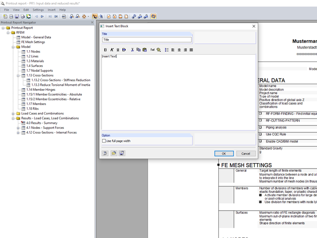
You can insert your own notes in the printout report. To do this, go to the printout report menu and click "Insert" → "Text Block."
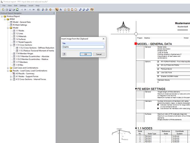
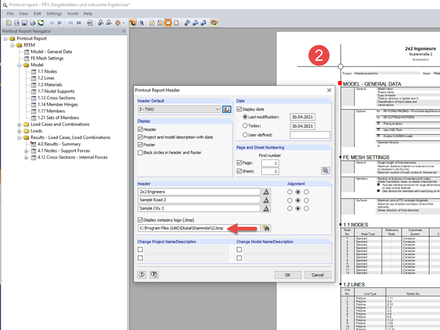
In RFEM and RSTAB, you can insert external images into the printout report.
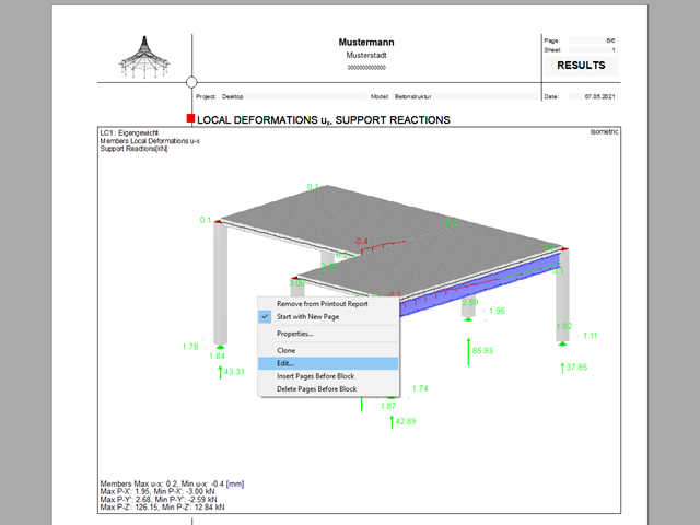
The printout report allows you to edit graphics subsequently.

RFEM and RSTAB save the input data, the FE mesh, the results, the printout reports, and the 3D gITF model preview, including all visual objects, in one file.
All Dlubal Software programs have access to the printout report environment.

The individually defined printout reports in an RFEM or RSTAB model can be displayed in different ways.
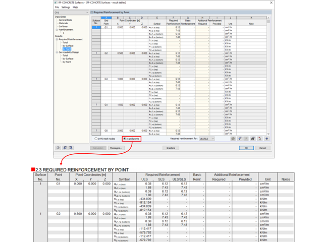
The results from RF‑CONCRETE Surfaces can be documented in tabular form in the printout report.

The SHAPE‑THIN and SHAPE‑MASSIVE cross-section programs are suitable for determining the cross-section properties of common thin-walled or thick-walled sections. These cross-section properties are also available for further analyses in RSTAB and RFEM.
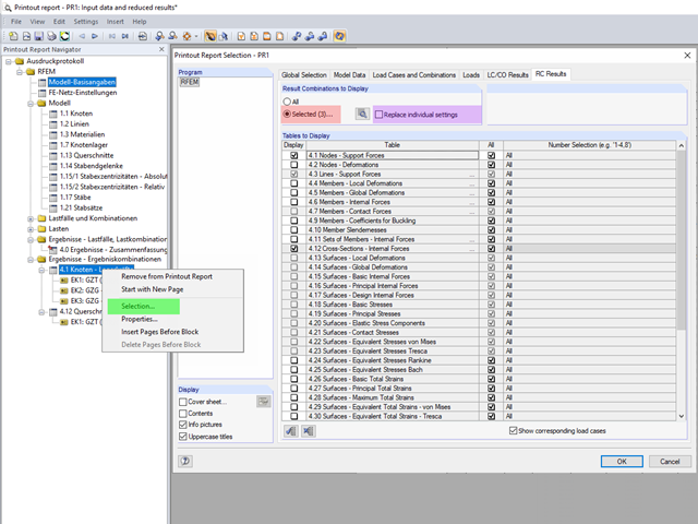
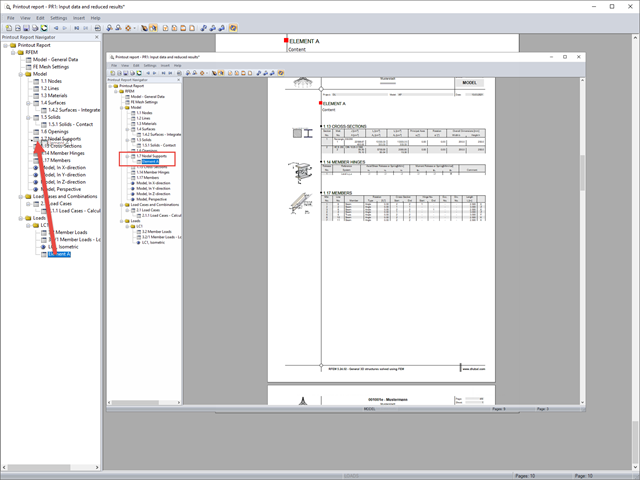
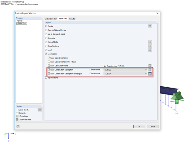
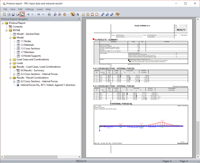
The content to be displayed in the loading and result tables can be managed in the global selection of the printout report (red).
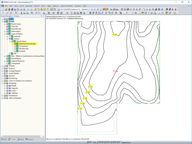
The results of an FEM calculation are usually documented by means of isobands and isolines in the graphical display of results. In the following, we will look at creating the results graphic for the black-and-white printout.

For a quick overview of the cross‑sections used, you can show the members in color sorted by cross‑section. Use the right mouse button in the work window to select "Colors in Graphics According to" → "Cross -Sections" from the shortcut menu. In the current program versions, you can use a panel with an editable color scale for this.
If you want to move individual elements or entire chapters in the printout report, there are various options.

Supports can be copied and moved using drag & drop, even if the "Move/Copy" function is not available in the shortcut menu. This applies to all kinds of supports: nodal supports, line supports, and surface supports. These can easily be assigned to further nodes, lines, or surfaces.

In RFEM, RSTAB, and SHAPE-THIN, you can create user-defined print templates ("Printout Report Template") and printout headers ("Report Headers"). These templates can also be transferred to other computers and used there.
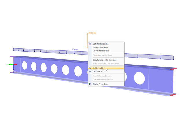
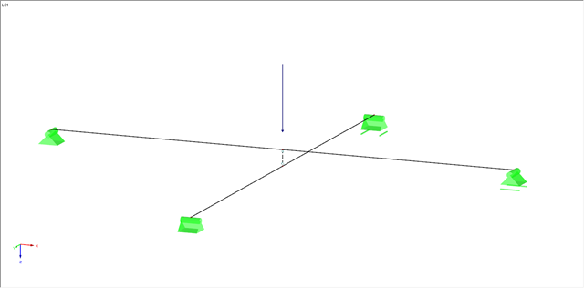
The display size of the load vectors can be adjusted quickly in the load shortcut menu: Right-click the load icon and select "Increase Display Size" or "Reduce Display Size" from the menu.
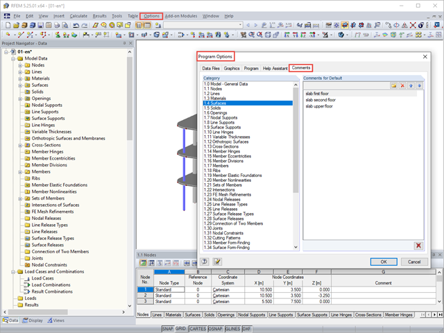
You can assign comments to each element in RFEM and RSTAB (structure element, load element, and so on). This can help to improve the overview and documentation of structures, as the comments appear in the printout report and, for example, certain objects can be filtered and displayed using the "Select Special" function.
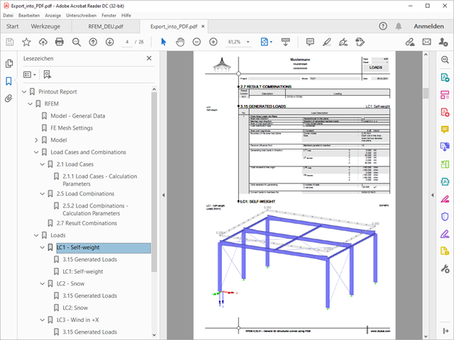
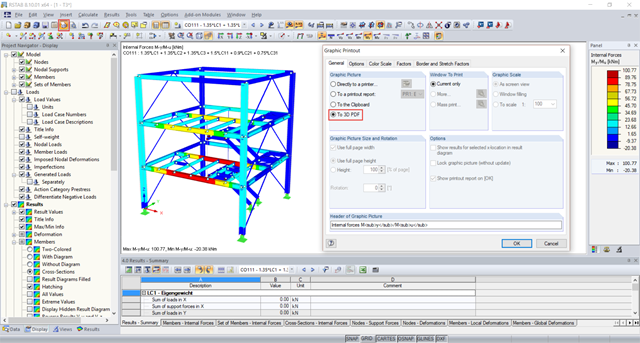
A PDF version of the printout report can be created in two ways. The most common way is to use a PDF printer that must be previously installed. The printer will be controlled like a real printer.
The selected increment of the load positions automatically increases the generated load combinations.
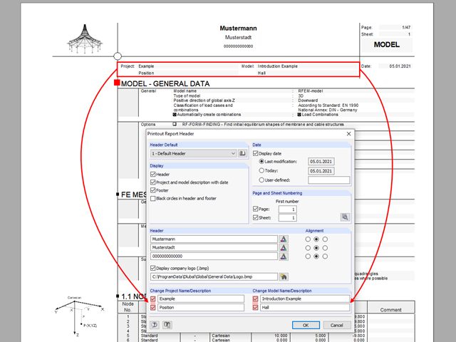
The name of the project/model from the General Data is shown in the header of the printout report by default. In RFEM 5 and RSTAB 8, the model name can be changed manually in the printout report independently of the actual name.
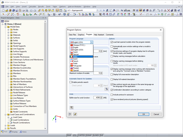
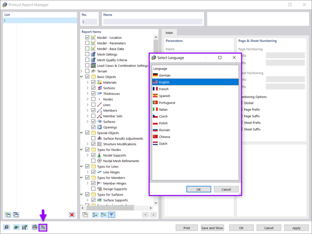
RFEM, RSTAB, and SHAPE-THIN are localized in eleven languages. All languages are available at no extra charge. The language of the program interface can be defined in the menu "Options" → "Program Options".
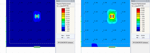
RFEM offers different options for the graphical display of results that have been determined in RF-CONCRETE Surfaces. This article gives an overview of these options.
From time to time, two intersecting beams overlap at a short distance. Such a structure raises the question, with regard to the modeling, of how it is possible to consider a contact with force transmission under compression between the two beams, while the contact under tension (for example, in case of a lifting top beam) should fail.
Printout reports created in RFEM and RSTAB can be transferred to VCmaster using a direct interface and further processed there. VCmaster (formerly BauText) is a word processing program for engineers. Calculations, drawings, photos, and documents from various sources can be easily compiled, managed and used again with VCmaster.
The 3D PDF functionality allows you to display three-dimensional models from RFEM or RSTAB in a 3D PDF.
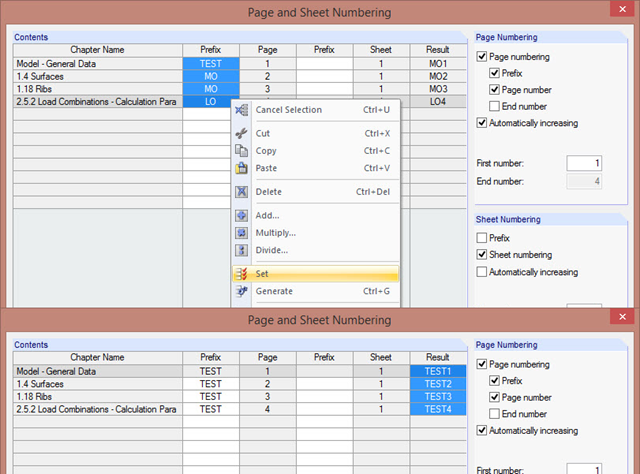
The "Page and Sheet Numbering" dialog box allows you to add a prefix to page and sheet numbering. It can be an abbreviation that specifies by chapter all model data in the numbering (for example, with "MO").
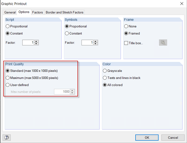
For a structural analysis printout in the usual DIN A4 page format, the default settings of 1,000 x 1,000 pixels graphic quality are completely sufficient. However, if the printout should be on a larger page format, you can increase the print quality to a maximum of 5,000 x 5,000 pixels in the Graphic Printout options, or specify a user‑defined value.